Become a member of our Forum, and gain access to a lot more information!
Become a member of our Forum, and gain access to a lot more information!
|
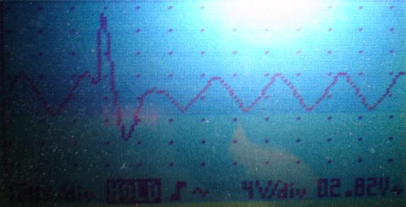
Hi Everyone, A Video Update is available, 40Mb. Click Here. This is the comple working Circuit for the Magnet Conditioning, only a few minor adjustments, like voltage levels, need to be done. In my opinion I have got the circuit right and producing the same effect as what Floyd had in the Sweet/Bearden Video. I think it is important to point out that under the Wave Tec Oscillator, in the Sweet/Bearden Video, Floyd had a "Black Box". I believe this box had some hidden Circuitry. I believe the cable in Floyds circuit that was connected to the Diode bridge came from this box. A picture of the wave I am currently getting is shown below. This is taken from a pickup coil that has a closer coupling to the AC wave. 4 Volts per division is not a correct indication of the power in this circuit, it is just an indication of the wave.
Some information I have gathered about
the Sweet/Bearden Video is documented in the below table:
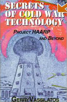
A very important piece of information I have had for a while but partially over looked is a Letter from Mr Sweet to John Morrison with some wave forms that I believe to be relevant to this letter. The coils in the conditioning circuit are constructed as follows: Inside Cylinder: One coil of 1.5mm wire with a total of 116 turns, two layers on a 160mm PVC Cylinder. Outside Cylinder: Two coils, each 80 turns of 2mm wire. The diameter of the Cylinder is 250 mm. The transformers are out of UPS's for computers. Both UPS's are around 700Va and are the older style of UPS's. One was a Powerware 5110 and the other was an APC UPS. The small step down transformer was out of an old Kitchen Drink Maker from memory. After working nearly every weekend for the two and a bit years on this project I went to Cairns for a holiday, a well deserved holiday. I tried to make a point of getting time to visit Lutec Australia to see the Lutec 1000. I was refused a visit and they told me that they only will let Investors look at the setup they have. I was a bit sore about that and had a bit of a grudge. Looking back on this I want to make all my information free to everyone and never hold any secrets like some others do. The good thing about my holiday was I came back fresh and with new ideas. I also read the book "Secrets of Cold War Technology - by Gerry Vassilatos" This book is a brilliant book and Gerry has done some very good research here. A lot of things clicked into place for me after reading this book.
Well more coming soon as always. |